|
|
Joint Stock Company
|

|
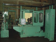
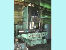
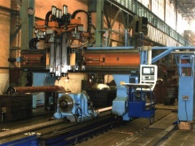
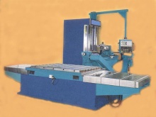
DRILLING MILLING BORING CNC MACHINES MODEL 2555PMF4
1. TECHNICAL DESCRIPTION
1.1. The machines can be used for drilling, boring, milling and treading by means of the tap with compensating device.
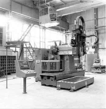
1.2. The arrangement of the machine includes:
- The stationary baseplate fixed on the foundation provided with T-slots for clamping the workpieces.
- Carriage, fixed at the foundation.
- The pillar with the sleeve, provided with possibility of longitudinal horizontal travel along the table guides (X axis).
- The spindle stock, provided with possibility of transverse horizontal travel along the sleeve guides (Y axis).
- The slide provided with possibility of vertical travel along the spindle stock guides (Z axis).
- Vertical spindle is mounted on the slide.
1.3. Feed is provided by X; Y; Z-axis travel.
1.4. Adjustable spindle and feed drives provide steeples spindle speed and feed rate changing.
1.5. The following types of displacement transducers are used in the machines:
- X-axis – for 2000 mm travel direct or indirect measurement transducer as per customer's choice, only direct measurement transducer for travel over 2000 mm.
- Y-axis – direct or indirect measurement transducer as per customer's choice.
- Z-axis – indirect measurement transducer.
1.6. Regular spindle design provides the tool clamping in the spindle cone ISO50. As to customers order the tool additionally can be clamped directly at the spindle nose by means of 4 threads M16, located on the diameter 101,6 mm and by outer diameter of the spindle nose 128,57h5.
1.7. Regular machine design provides tool clamping mechanism and tool tails according to manufacturers drawings. As to customers order the tool clamping mechanism can be supplied in accordance with DIN or ANSI standard.
1.8. The tool clamping mechanism drive can be supplied according to customers choice:
- Hydraulic
- Electromechanical
1.9. The coolant can be directed to the tool:
- through the slide
- through the nozzles on the displaceable bars on the spindle stock
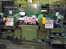
1.10. The machines with X-travel 4000 mm and over are equipped with control panel and operators platform located at the pillar.
1.11. As to customers choice the machines can either be equipped with automatic tool changer or supplied without it.
1.12. Tool disk type tool changer is located on the sleeve and is controlled by regulated motor (W axis).
1.13. The tool changing movements are provided by spindle (Y and Z axis) and rotation of tool changer (W axis).
The dimensions of tools in each sell of tool changer:
The dimensions of tools in the sell of tool when previous and next sells are empty:
Maximum tool weight – 15 kg Number of tools in the changer – 24 pieces Tool changing time – app. 30 seconds (spindle in Y=0 and Z=0 position) |
1.14. Regular machines design - voltage 380V, 50HZ. Other voltage is also possible in conformity with customers order.
1.15. CNC unit model and functions are to be determined while concluding the contract between the supplier of CNC unit and the manufacturer of the machine and they are agreed with the customer of the machine.
1.16. Number of axis controlled by CNC – 4 (3 linear and 1 rotary for tool changer).
1.17. Number of axis controlled by CNC simultaneously – 2 linear axis.
1.18. As to the order of the customer the machines can be supplied without CNC control unit and without electrical equipment – in case the customer is going to put his own CNC equipment.
2. TECHNICAL DATA
| NAME of parameter / dimension | Unit | 2555PMF4 |
|---|---|---|
| Drilling capacity for steel | mm | 50 |
| Counter boring capacity for steel | mm | 80 |
| Boring capacity | mm | 200 |
| Tapping capacity for steel | mm | M48x5.5 |
| Removed volume while steel milling | sm3/min | 300 |
| Length of the table surface | mm | 2000 and over subjected to discrete 2000 mm |
| Width of the table surface | mm | 1250 |
| Max table load | Kg/m | 10000 |
| Distance from spindle nose to table | 1000 | |
| Spindle taper | ISO50 | |
| Pillar travel – X axis | mm | 2000 and over subjected to discrete 2000 mm |
| Spindle stock travel – Y axis | mm | 1250 |
| Slide travel – Z axis | mm | 630 |
| Spindle speed | Rpm | 15 - 2500 |
| Pillar, spindle stock, slide feed | Mm/min | 5 - 6000 |
| Pillar rapid movement | M/min | 10000 |
| Spindle stock rapid movement | M/min | 10000 |
| Quill rapid movement | M/min | 6000 |
| Spindle torque | NM | 710 |
| Pillar feed force | N | 5000 |
| Spindle stock feed force | N | 5000 |
| Slide feed force | N | 20000 |
| Spindle motor power | kW | 15 |
2.2. Linear positioning accuracy.
| Name of the axis | Travel, mm | Accuracy, mm |
|---|---|---|
| Pillar travel – X axis | 2000 4000 6000 8000 |
± 60 ± 50 ± 50 ± 50 |
| Spindle stock travel – Y axis | 1250 | ± 50 |
| Slide travel – Z axis | 630 | ± 60 |
3. COMPLETE EQUIPMENT
3.1. Regular complete equipment set includes:
- Pieces for securing on the foundation
- Tools for maintenance
- Spare parts
- Instruction for maintenance
3.2. According to customers order can be supplied in addition :
- Tool changer
- Telescopic cover for table guides protection
- Clamping devices for work piece